Cartridge kit
Introduction
This project is a cost-reduced version of the Multicartridge, meant for hobbyist who would like to build their own cartridge and are comfortable using a soldering iron. The cartridge is designed such that the majority of the components can already be assembled by the PCB manufacturer (e.g. using a so-called assembly service). The user only needs to solder in three more through-hole components and the cartridge is ready to use.
Components
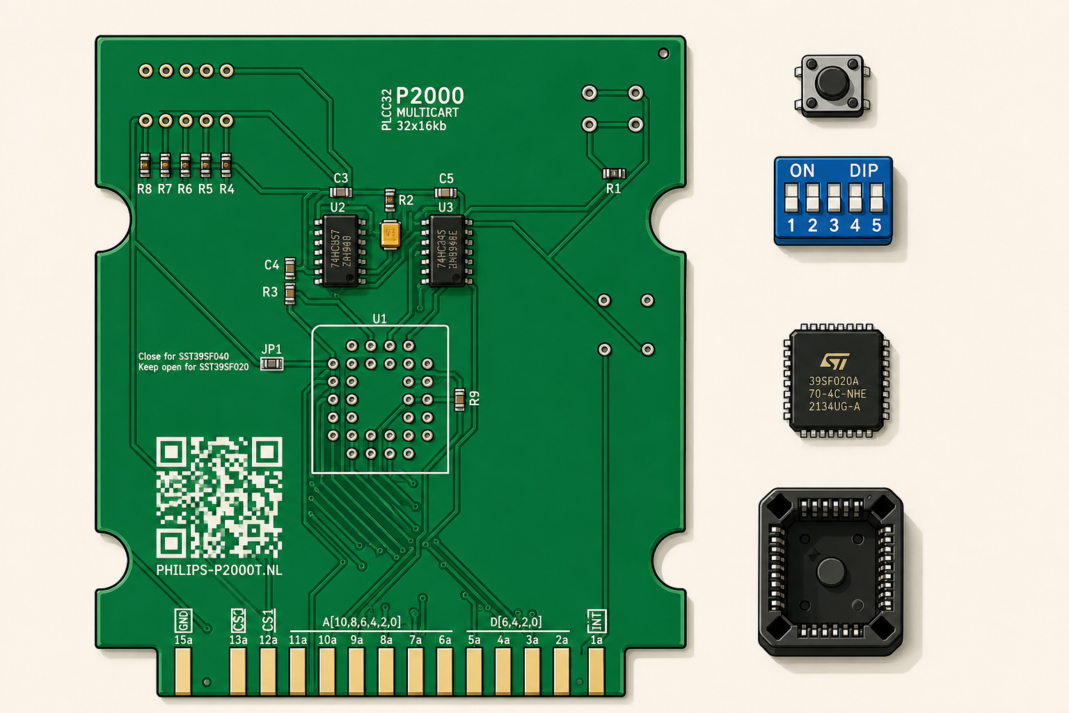
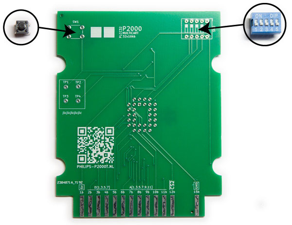
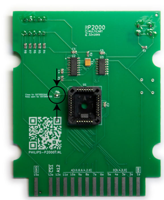
Before starting building your cartridge, check that all components are present. You need one PCB with the majority of the SMD components already soldered as shown in Figure 1.
Furthermore, you need the following three through-hole components (see Figure 1):
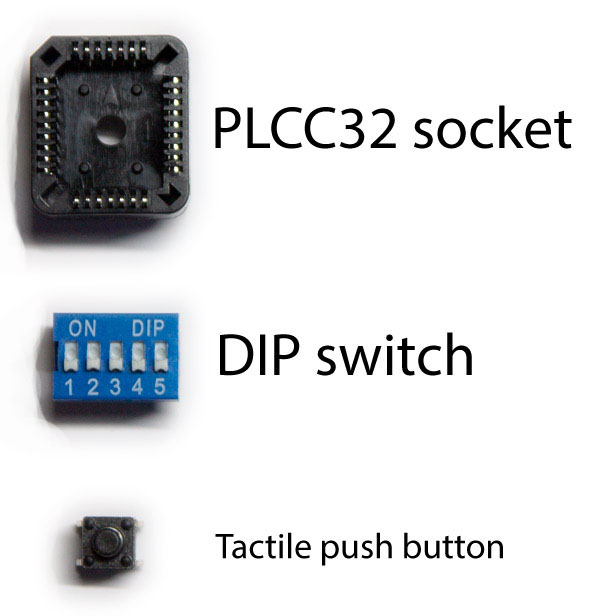
- PLCC32 socket
- DIP switch
- Push button
Soldering guide
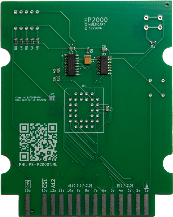
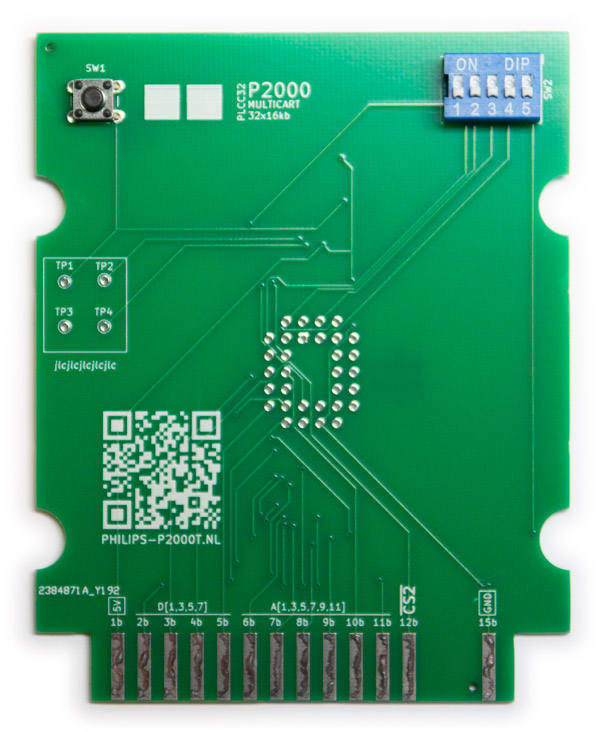
Insert the tactile push button and the DIP switch on side B of the PCB in SW1 and SW2, respectively, and solder the pins (see Figures Figure 2 and Figure 2).
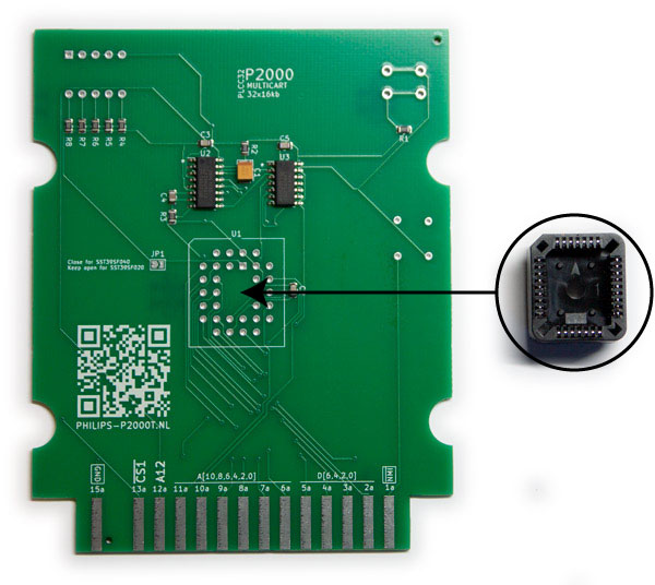
Insert the PLCC32 socket on side A of the PCB in U1 and solder the pins.

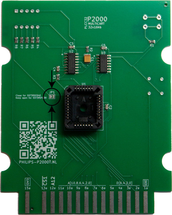
If you intend to use the 512kb SST39SF040 chip, place a solder blob on JP1 such that both ends are shorted.
Carefully inspect your solder points to see if they look properly and you are all done.
Casing (optional)
The PCB can be nicely embedded in a 3d-printable case, as found here. The recommended settings for the prints are:
- 0.4mm nozzle
- 0.15mm layer height
- 20% infill
For the casing, you need:
- 4 M3 threaded inserts
- 4 M3x8mm screws
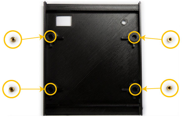
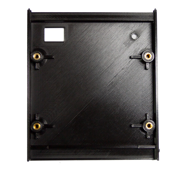
Heat up your soldering iron to and gently push the threaded inserts into the plastic holes of the top side of the case as shown in Figure 5 and Figure 5.
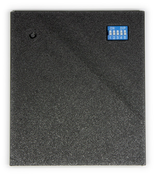
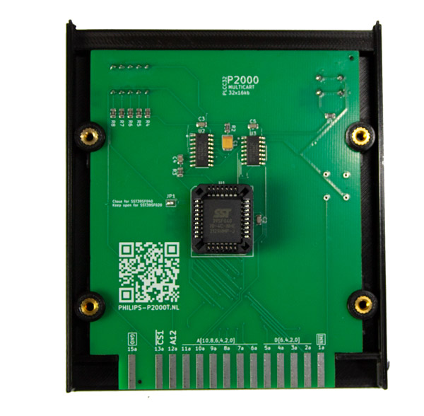
Place the PCB inside the top case and gently push it until it snaps into place. Ensure that the A side, i.e. the side containing the chips, is facing towards you and that the push button and the dip switch are on the opposite side, as shown in Figure 6.
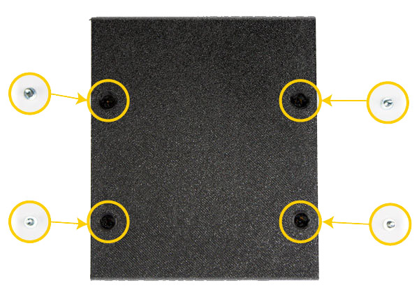
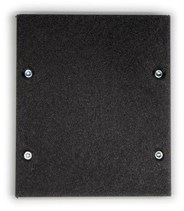
Align the bottom half of the cartridge enclosure with the top and gently apply pressure until they both half snap together. Insert the four M3x8mm screws (see Figure 7 and Figure 7) and fasten them.
That is it. You are done. Turn over the cartridge and admire your work.