SD-card cartridge
Introduction
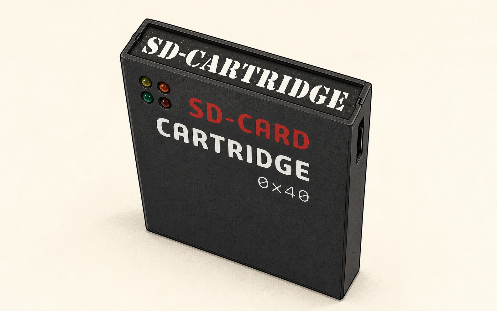
Perhaps the most elegant solution for loading CAS files into your P2000T is via a cartridge that hosts an SD-card slot. Even the smallest SD-cards have enough capacity to store the complete P2000T tape archive. Reading from such an SD-card is non-trivial and requires both a hardware solution to interface with the I/O port of the P2000T as well as a software solution to navigate through the files hosted on a FAT32 partition. This page explains both parts in more detail.
Preparation
The SD-card cartridge works very similar as compared to the data cartridge. A modified BASICNL cartridge is prepared that loads a LAUNCHER program from the ROM chip on the SD-card cartridge into memory. Next, this launcher program is executed which interfaces with the SD-card. To set-up this infrastructure, one needs to prepare a SLOT1 cartridge with the modified BASICNL rom and one needs to flash the launcher program on the ROM chip of the SD-card cartridge.
Summarizing, check that you have the following ready
- A SLOT1 cartridge with the modified BASICNL application.
- A SLOT1 cartridge with the flasher application.
- The SD-card cartridge with a FAT32-formatted SD-card and the launcher application flashed to its internal ROM.
Creating the SLOT1 cartridges
First, we need to construct two SLOT1 cartridges, being the modified BASIC cartridge and the flasher. The BIN files for these two cartridges can be obtained via the links below.
Downloads
Upload these two BIN files to different ROM slots on the ZIF cartridge. A detailed guide on the procedure can be found on the page describing the ZIF cartridge.
Flashing the launcher onto the ROM chip
Next, we need to prepare an SD-card and place the LAUNCHER.BIN on this SD-card
in its root directory.
Place the LAUNCHER.BIN file in the root directory of the SD-card. The latest version of the LAUNCHER.BIN file can be downloaded via the link below.
Downloads
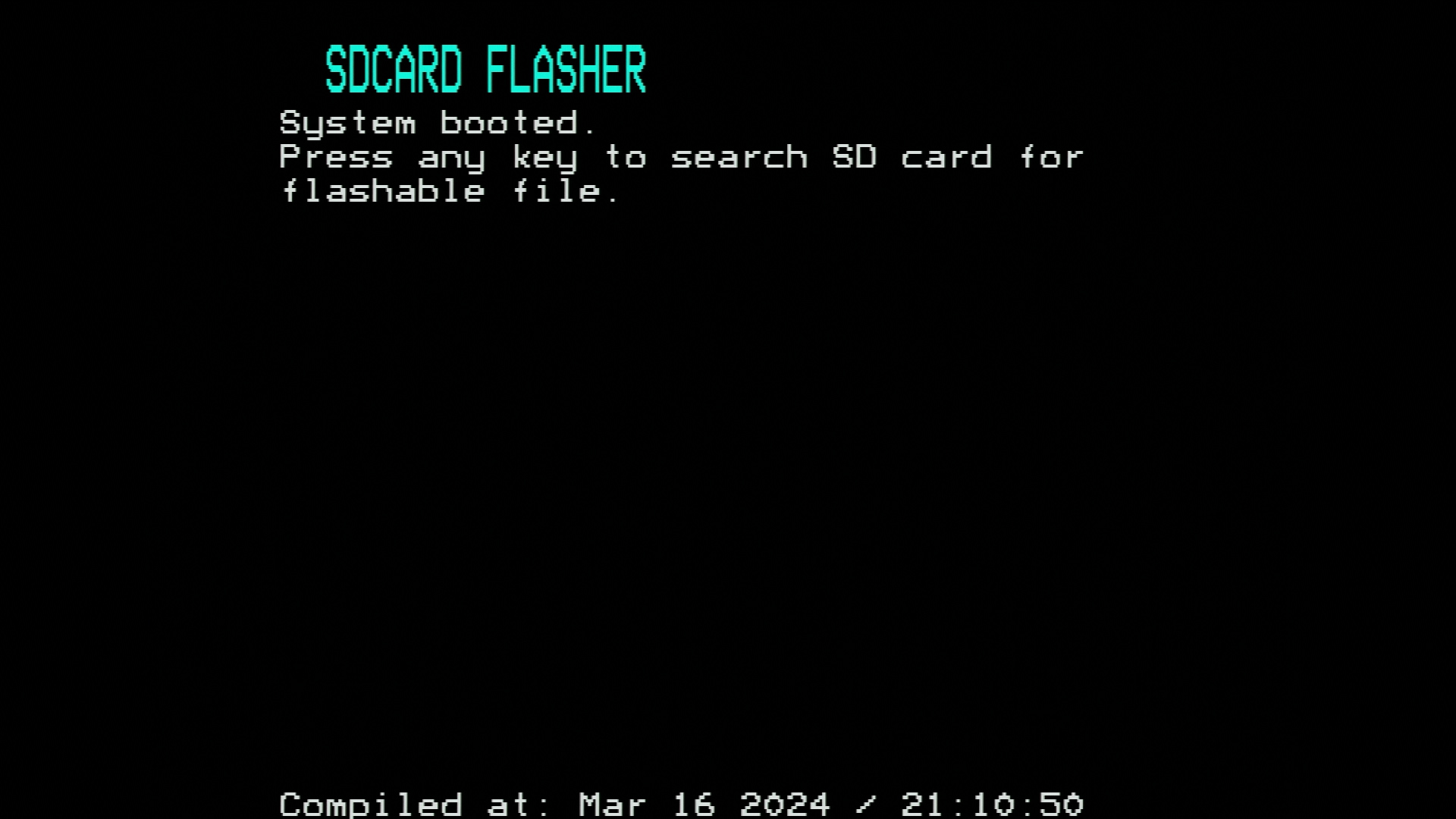
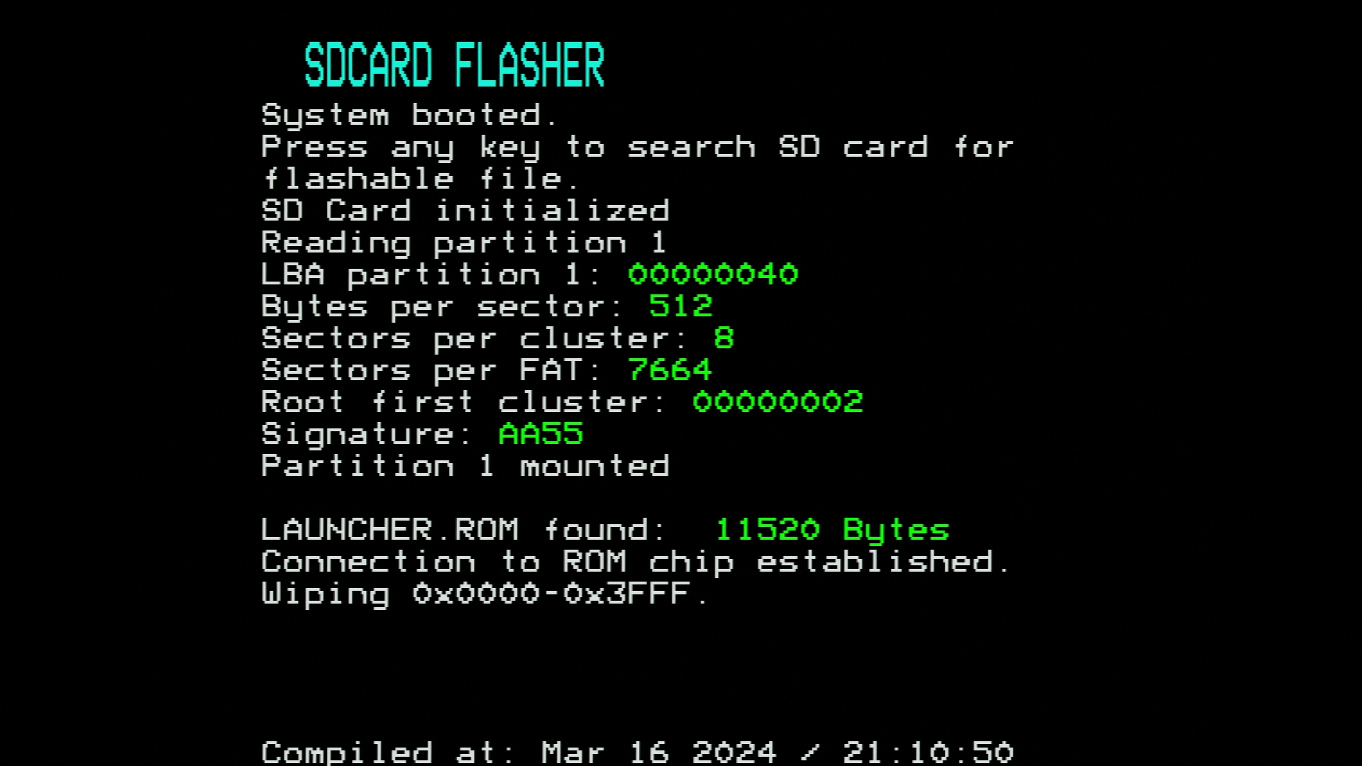
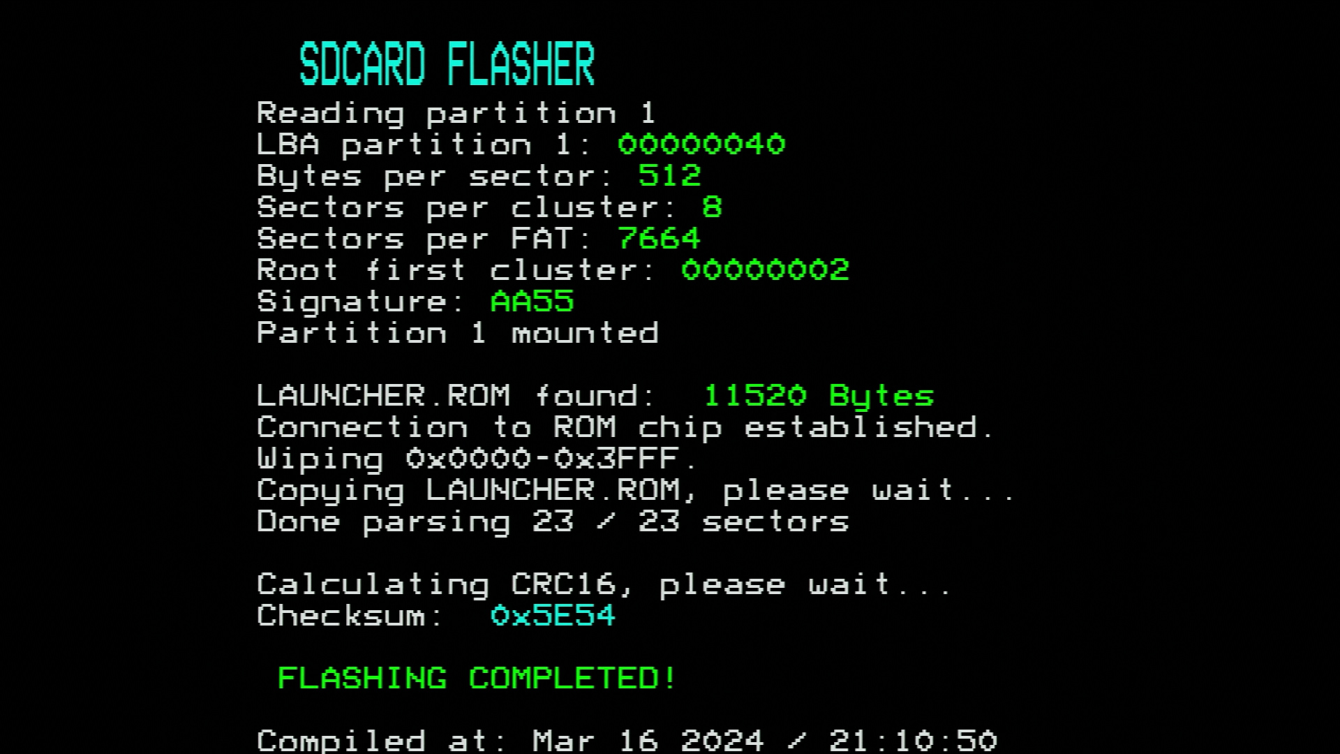
Insert the SLOT1 cartridge with the flasher and the SD-card cartridge in SLOT2
and turn on your P2000T. Hit any key to start interfacing with the SD-card and
search for a file called LAUNCHER.BIN. If such a file is found, the file will
be copied to the internal ROM chip of the SD-card cartridge. Any previous data
corresponding to previous versions of the launcher will be automatically
wiped. After copying the file to the ROM chip, a CRC-16 checksum is
automatically generated and used for verification purposes.
LAUNCHER.ROM is found. 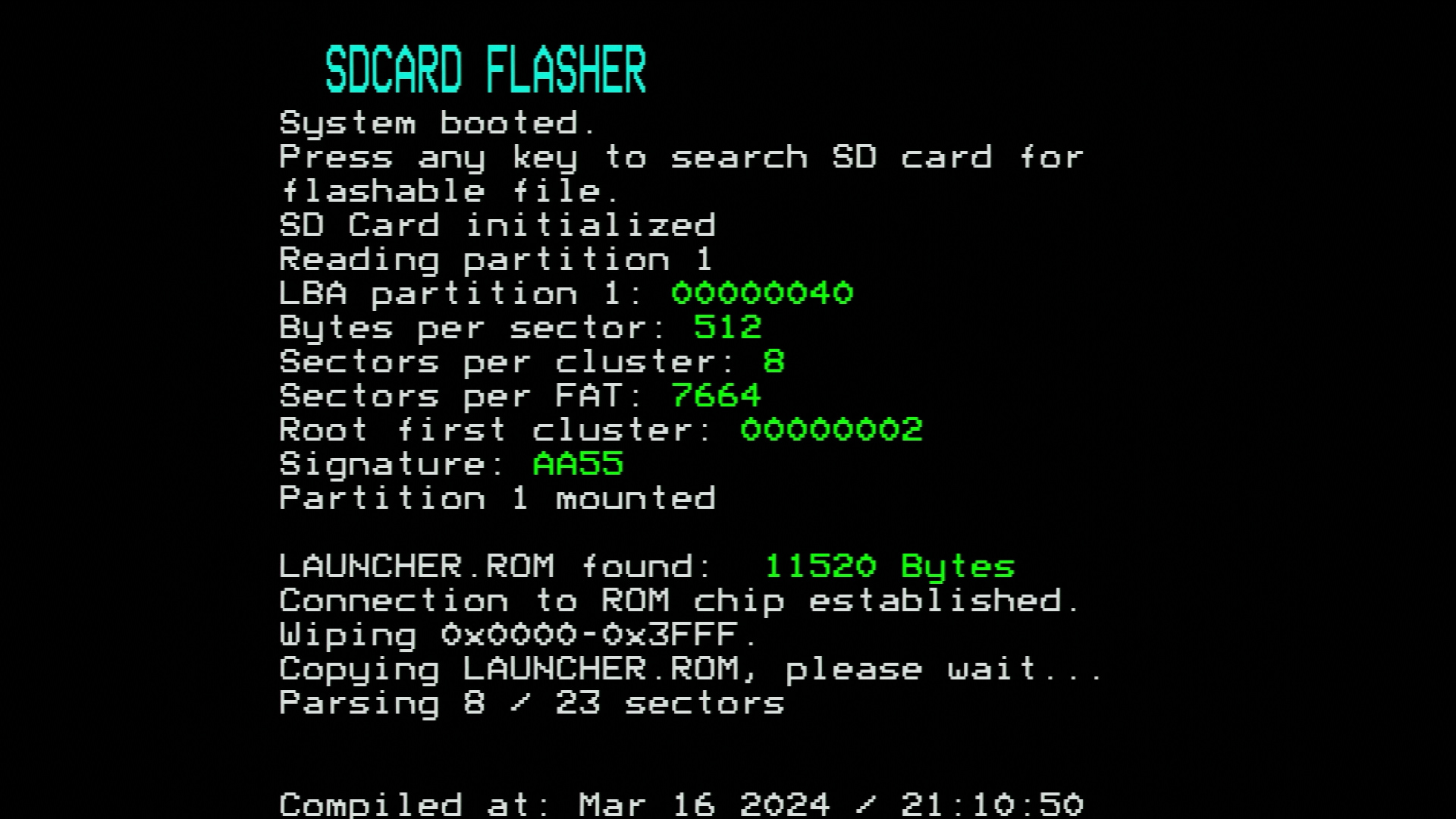
Launching CAS programs from the SD-card cartridge
Programs can be loaded from the SD-card and executed using the launcher. To load the launcher into memory, the P2000T requires a modified BASICNL cartridge (see the instructions under preparation on how to prepare such a cartridge) in SLOT1. This modified BASICNL cartridge will copy the launcher from the internal ROM chip on the SD-card cartridge to memory and run it.
Loading a program from the SD-card is fairly easy. There are only three commands
one needs to be know: ls, cd and run.
cdis used to navigate to (sub)directories.lsis used to show a listing.runis used to start a program.
Per directory, all items inside the directory have a number (called an index)
which starts at 1. On execution of a ls command, these indices are shown. To
change directory, type cd followed by the index number. For example, cd 4
will go to the fourth entry. If that entry is a subdirectory, the launcher jumps
to that folder. To run a program, one types run followed by the number. For
example, run 107 will run the 107th entry in the folder. In the example shown
in Figure 2, this corresponds to the Tetris
program.
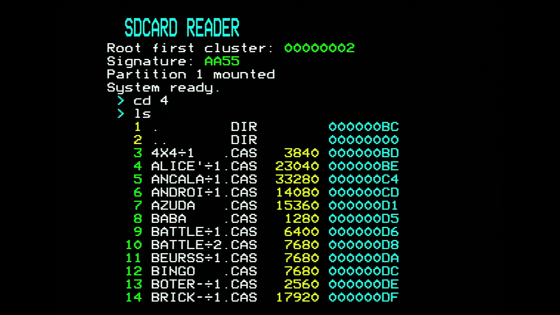
4 and runs ls to get a listing of the subdirectory contents. 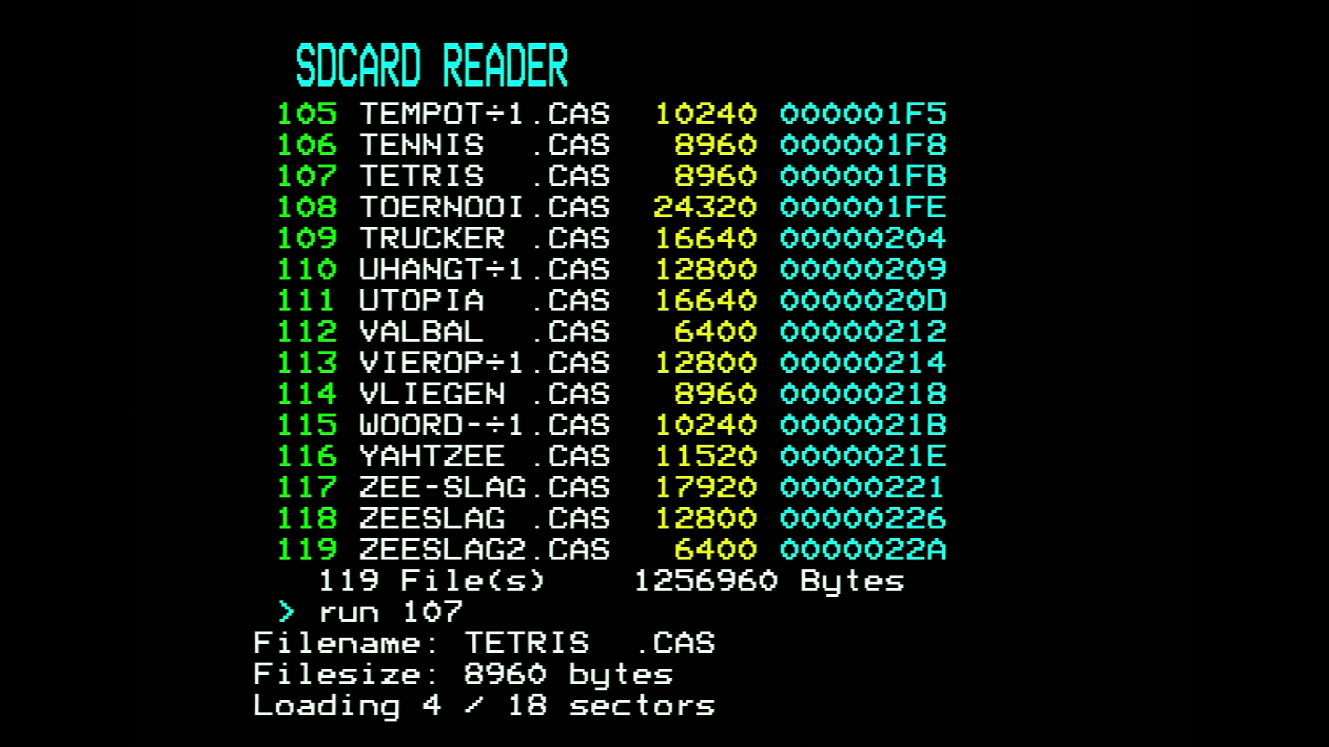
107 (Tetris) and the program is transferred from the SD-card to the external memory chip. 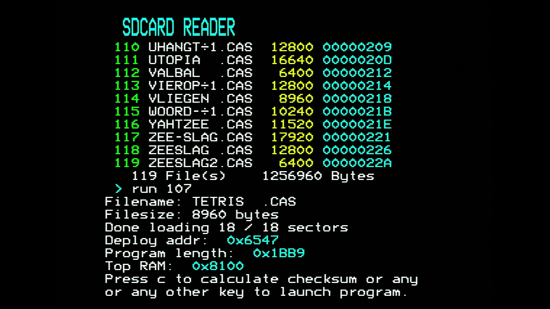
Once the CAS file is loaded into memory and executed, one will not return back to the launcher once the BASIC program is terminated. To restart the launcher, simply reset the machine.
Running PRG files from the SD-card
Besides running CAS files, it is also possible to execute special .PRG files.
These files are loaded from the SD-card and placed into memory at position
0xA000-0xDCFF.
In contrast to CAS files, upon termination of these programs you will return to
the launcher and one can open another .PRG file or a CAS file. Launching a
.PRG file is completely synonymous to launching a CAS file, simply use run <index> where <index> refers to the index of a .PRG file. The launcher
will automatically verify the integrity of the .PRG file by calculating its
checksum. Only upon a valid checksum will the program start.
Currently, there are not many .PRG programs made, but one program that is
potentially useful and relevant is CASDUMP.PRG. This program allows the user
to copy files from the cassette tape to the SD-card. See this section for more information.
Copying cassette data to the SD-card
To copy the contents of a cassette tape to the SD card, first download the
program CASDUMP.PRG via the link as shown below and place it on the SD-card.
Next, ensure a directory called DUMPS exists on the SD-card and is located in
the ROOT directory of the SD-card. You will need to create this directory on
your computer or laptop. Be sure it says DUMPS without any trailing spaces and
preferentially all in capitals.
Insert the SD-card into the SD-card cartridge and execute the launcher
application. Navigate to the folder containing CASDUMP.PRG and run it via run <index> where <index> refers to the index of CASDUMP.PRG.
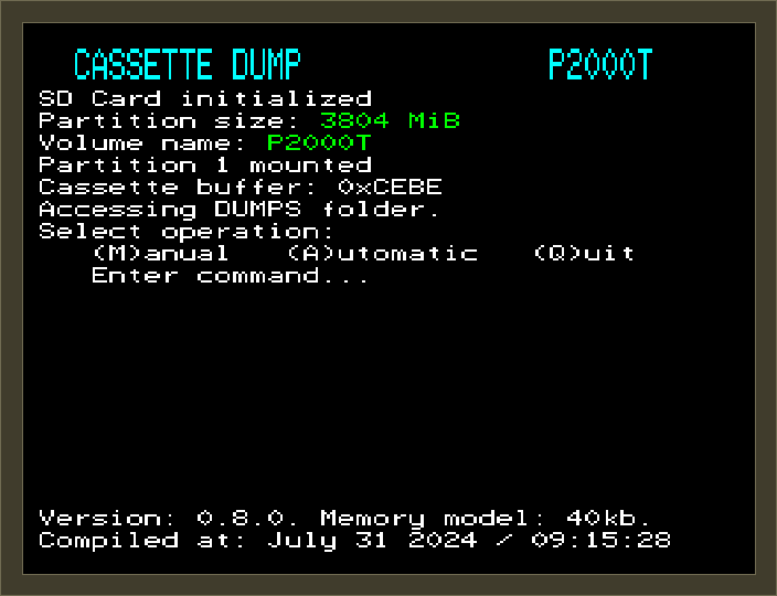
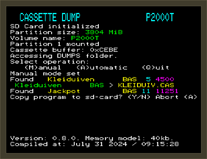
Upon execution, the Cassette Dump program will verify whether it can find a
folder called DUMPS and if so, the cassette dumping routines can start. A
number of screenshots showcasing the process are provided in Figure 3. At the very start, the program will ask the user whether
they want to perform cassette file extraction using automatic or manual
mode. In the automatic mode, the program aims to read the whole cartridge and
copy over any program it can find. In manual mode, for every file encountered,
the user will be asked whether they want to store the file. In Figure 3, the process corresponding to manual mode is shown.
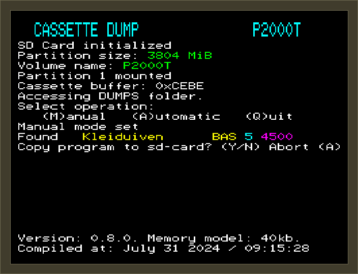
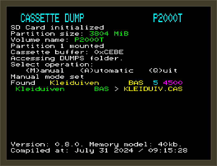
A CAS file has a 16 character description whereas the SD-card uses the old
MS-DOS 8.3-style notation. As such, Cassette Dump will take the first 8
characters of the 16-character description and checks the SD-card whether a such
a file already exists. If not, the cassette data is written to this file. If it
does exists, the program tries to rename the file by replacing the last
character by a 0. If this file also exists, it will replace the last character
by a 1, and so forth, until all options have been tried. Any invalid
characters, e.g. a question mark ? will be automatically replaced by valid
8.3-style characters.
Cartridge commands
Below, an overview of the commands is provided.
| Command | Description |
|---|---|
ls |
List contents of current folder |
lscas |
List contents of current folder, listing contents of CAS files |
cd <number> |
Change directory |
run <number> |
Run .CAS file |
hexdump <number> |
Performs a 120-byte hexdump of a file |
fileinfo <number> |
Provides location details of a file |
ledtest |
Performs a quick test on the read/write LEDs |
stack |
Show current position of the stack pointer |
dump<XXXX> |
Perform a 120-byte hexdump of main memory starting at 0xXXXX |
romdump<XXXX> |
Perform a 120-byte hexdump of cartridge ROM starting at 0xXXXX |
ramdump<XXXX> |
Perform a 120-byte hexdump of cartridge RAM starting at 0xXXXX |
Technical details
Cartridge features
In Figure 4, the schematic of a SLOT2 SD-card interface is shown. The schematic is fairly dense, so we will break it down into a few separate building blocks.

Parallel to serial conversion
Communication with SD-cards proceeds via the SPI protocol. The SPI protocol is serial by nature, while the Z80 exposes a parallel data bus. One way to bridge that difference is bit banging, where the Z80 toggles the serial lines in software. That works, but it is rather inefficient: for each instruction we effectively use only 1 of the 8 available data bits. A nicer approach is to use the full 8-bit data bus whenever the Z80 performs an I/O operation. To do that, the cartridge uses one parallel-in-serial-out (PISO) and one serial-in-parallel-out (SIPO) shift register (74HC165 and 74HC595, respectively).
When communicating with the SD-card over the serial connection, we need to be able to transfer or receive 8 bits in roughly the time it would normally take the Z80 to complete one I/O instruction. The parallel-to-serial interface therefore has to run at a higher clock frequency than the Z80 itself. In this implementation, a timer circuit is driven by a 16 MHz oscillator. That frequency is divided by two using a 74HC163 counter, and the resulting clock drives both the shift registers and the SPI clock signal. The shift registers receive the inverted clock, which is delayed by half a clock cycle compared with the regular clock. The SD-card receives the regular clock, so the card is half a clock cycle ahead of the shift registers.
The SPI protocol is a synchronous protocol, so essentially bits of data are exchanged between the host device (master) and the SD-card (slave) at the same time. In this design, that exchange happens one byte at a time. To send a byte from the Z80 to the SD-card, the byte is first loaded into the PISO register. The timer circuit is then started and emits exactly 8 clock pulses, shifting the byte out to the SD-card. At the same time, the SIPO register receives 8 bits from the SD-card and stores them. The Z80 can then retrieve the received byte by reading from the SIPO register.
This also means that the Z80 must keep sending data even when it only wants to receive data from the SD-card, for example while reading a 512-byte block. The nice part of this design is that the Z80 does not need to bit-bang every clock edge itself. It can continue with other work, such as fetching the next instruction, while the SD-card circuitry performs the serial transfer in parallel.
I/O selection
The SD-card cartridge hosts a number of devices and chips which all require
their own I/O address for efficient communication. Using two 3-to-8 line
decoders
(74HC138),
the lower byte of the I/O address can select up to 16 devices. In practice, only
11 of these 16 lines are used. They are mapped to I/O ports 0x60-0x6F, while
the upper byte is checked by a
74HC85
comparator. The complete port map is listed below.
| Port number | Function | R/W |
|---|---|---|
0x60 |
Serial read/write | R/W |
0x61 |
Start clock circuit | W |
0x62 |
Set MISO pull-up/down | R/W |
0x63 |
Set/unset CS on SD-card | R/W |
0x64 |
LEDs | R/W |
0x65 |
not used | N/A |
0x66 |
not used | N/A |
0x67 |
not used | N/A |
0x68 |
Lower address byte | W |
0x69 |
Upper address byte | W |
0x6A |
Bank register ROM | W |
0x6B |
Bank register RAM | W |
0x6C |
ROM chip | R/W |
0x6D |
RAM chip | R/W |
0x6E |
not used | N/A |
0x6F |
not used | N/A |
The Z80 talks to these devices using the
IN and
OUT instructions. For
example, to send 0xFF to the SD-card and read back the resulting byte, we
could use:
ld a,0xFF
out (0x60),a     ; set all ones
out (0x61),a     ; start timer circuit, value in register a is not used
in  a,(0x61)     ; receive result from SD-card
RAM and ROM chips
The SD-card cartridge uses a SST39SF010 and a 62128 as the ROM and RAM chips, respectively. Both these chips have a capacity of 128kb. The ROM chip stores the launcher, while the RAM chip is used as temporary storage for CAS programs. Because the Z80 I/O interface only gives us 8 bits at a time, the address for these memory chips is stored in two 8-bit registers (74HC273) and one 2-bit register (74HC74). The two 8-bit registers store the lower and upper address byte, and the 2-bit register is used for bank selection. Each bank therefore corresponds to 64kb of memory. Both the ROM and RAM chip share the same 16-bit address registers, which in practice does not cause any trouble.
Reading from the ROM and RAM chips works in much the same way. First, the bank
is selected by writing 0 or 1 to 0x6A for the ROM chip, or to 0x6B for
the RAM chip. Next, the 16-bit address is set by writing the lower byte to
0x68 and the upper byte to 0x69. Once the address is set, the Z80 can read
from 0x6C for the ROM chip or from 0x6D for the RAM chip. For example,
reading a byte at address 0xAA55 from the ROM chip looks like this.
ld a,0x00
out (0x6A), a    ; set first bank (bank 0)
ld a,0x55
out (0x68), a    ; set address lower byte (0x55)
ld a,0xAA
out (0x69), a    ; set address upper byte (0xAA)
in  a,(0x6C)     ; read from chip address 0xAA55
Writing to the RAM chip is equally straightforward: use an OUT instruction
instead of an IN instruction. The example below writes 0x00 to address
0xAA55.
ld a,0x00
out (0x6B), a    ; set first bank
ld a,0x55
out (0x68), a    ; set address lower byte (0x55)
ld a,0xAA
out (0x69), a    ; set address upper byte (0xAA)
ld a,0x00
out (0x6D), a    ; store byte in A into RAM chip at 0xAA55
Writing to the ROM chip is a bit more involved and requires a sequence of instructions. More details about that sequence can be found in the datasheet of the SST39SF0x0 family of chips.
SD-card
With the hardware described above, the Z80 can now communicate with the SD-card. Communication is command based: the host sends a command packet to the card, and the card returns a response. These command packets are sent through the I/O port.
The exact procedure is described in the official document “Physical Layer Simplified” which can be found via this page. Following Figure 4-2 in that document, the initialization sequence needed before reading blocks is roughly as follows.
- Set CS to low on the SD-card
- Send at least 74 pulses of
1to the SD-card - Send
CMD0to the SD-card ({0|0x40,0,0,0,0,0x94|0x01}) to put the card in SPI mode and check for a validR1response. - Send
CMD8to the SD-card ({8|0x40,0,0,0x01,0xaa,0x86|0x01}) to send the interface condition (argument0x1AA) and check for a validR7response. - Send
CMD55to the SD-card ({55|0x40,0,0,0,0,0x00|0x01}) for an application specific command and check for a validR1response. - Send
ACMD41to the SD-card ({41|0x40,0x40,0x00,0x00,0x00,0x00|0x01}) to send the host capacity support information (argument0x40000000) and check for a validR1response. - Repeat steps 5 and 6 until a response of
0x00is received. This typically takes about 2-3 calls. - Send
CMD58to the SD-card ({58|0x40,0,0,0,0,0x00|0x01}) to read the OCR register and read theR3response. - The card is now ready to receive
CMD17commands which request 512 byte blocks from the card.
FAT32 file system
The SD-cards used with this cartridge are formatted as FAT32. To navigate folders and access files, the launcher needs to understand the basic structure of that filesystem. Luckily, FAT32 is relatively simple and well documented. We will not go into every detail of the storage format here; the goal is simply to give a brief overview of how files are found and retrieved.
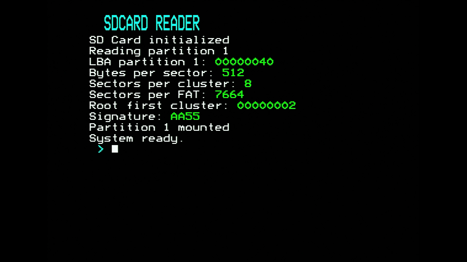
- The first 512 bytes of the SD-card, i.e. the master boot record (MBR), is loaded. The MBR contains information on the partitions.
- From the MBR, the logical block address (LBA) of the first partition is read.
- From the partition table, the number of bytes per sector, the sectors per cluster, the reserved sectors, the number of FATs, the sectors per FAT, and the LBA of the root directory are read and stored for later use.
- Once the LBA of the root directory is known, the launcher can read the metadata for the files and subdirectories in that directory. File entries point to the actual file data. Subdirectory entries point to the metadata for the contents of that subdirectory.
- Based on the file metadata, a sequential list of clusters can be constructed that contains the actual file data. These clusters are then traversed, and all sectors belonging to those clusters are read and transferred to the P2000T.
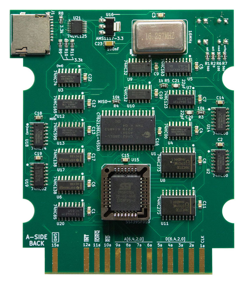
PCB lay-out
An image of the PCB is shown below. As you can see, there is not much free space left on this board. The SST39SF010 chip sits in the PLCC32 socket near the center, with the 128kb RAM chip directly above it. The 16 MHz oscillator is located in the upper-right area. In the upper-left area, an SD-card interface board is mounted. This small board performs the level shifting between the 5V signals on the cartridge PCB and the 3.3V signals used by the SD-card. Directly to the right of the PLCC32 socket, the 2x74HC273 buffer chips store the address bus for both the ROM and RAM chips.
References
- https://www.ecstaticlyrics.com/electronics/SPI/fast_z80_interface.html
- https://electronics.stackexchange.com/questions/77417/what-is-the-correct-command-sequence-for-microsd-card-initialization-in-spi
- http://www.rjhcoding.com/avrc-sd-interface-1.php
- https://www.pjrc.com/tech/8051/ide/fat32.html
- https://en.wikipedia.org/wiki/File_Allocation_Table#FAT32