Videoports
P2000T model
Interface
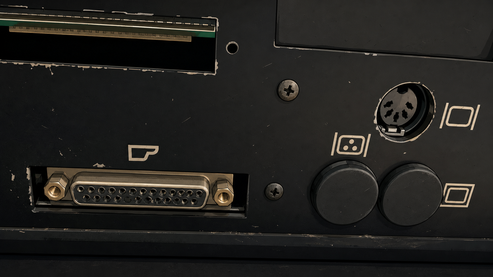
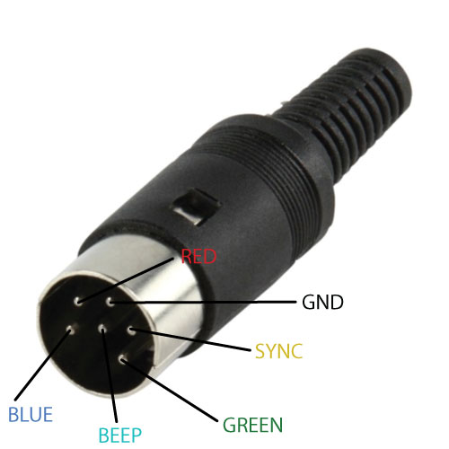
The P2000T has a RGBS type of video output offered via a DIN-6 connector (DIN 45322) at the back of the P2000T (see Figure 1).
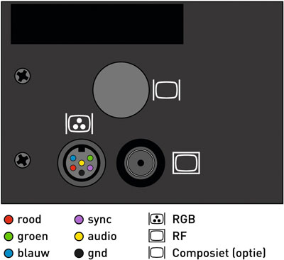
This port offers separate red, green and blue signals as well as a combined sync (CSYNC) that indicates horizontal and vertical refresh. The 1-bit audio (beep) is also available via this port. An overview of the pinout is provided in Figure 2.
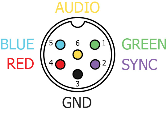
If you want to build a connector for this socket, use the diagram as shown in Figure 3 for the correct wiring. Observe that the schematic as seen in Figure 3 is essentially a mirror image of the schematic as seen in Figure 2.
Regular or inverted sync signal
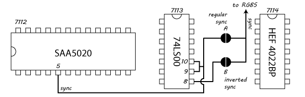
The P2000T mainboard has two jumper pads located in between the 74LS00 and
HEF 4022BP chips (#7113 and #7114, respectively) as shown in
Figure 4. Depending on which
of these two pads is closed by a solder blob, the sync signal outputted on the
RGBS port is either the regular sync signal as provided by the SAA5020 chip
or an inverted signal via one of the NAND gates on the 74LS00. If you want
to use your P2000T to connect to a TV over a SCART connector, ensure you
provide the regular (non-inverted) signal by closing pad A and opening
pad B.
74LS00 and the
HEF 4022BP chips. When solder pad A is closed, a non-inverted sync signal
is provided to the RGBS port. When solder pad B is closed, an inverted sync
signal is provided instead.Connecting to HDMI display
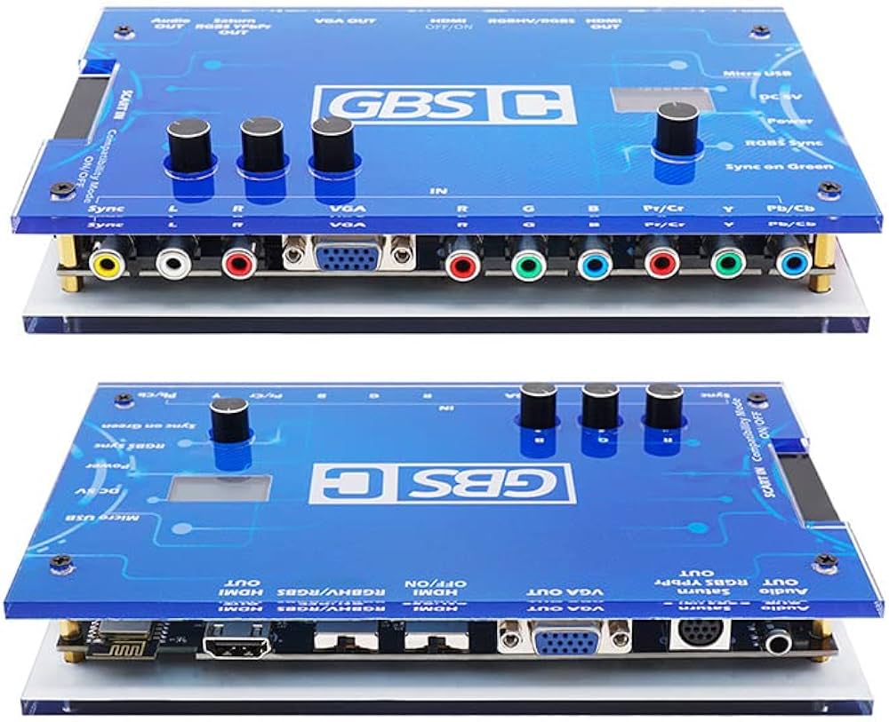
The output of this port can be directly connected to a monitor supporting the RGBS format such as the Commodore 1084S, but also to a SCART connector or even to the GBS-Control (see Figure 5) which can convert the signal to HDMI. The advantage of HDMI output is that you can use a HDMI video capture device to record the screen of your P2000T.