
Serial communication with the Philips P2000C
The Philips P2000C has a DB25 serial interface connector on its rear side, which can be used for communication over the RS-232 protocol. This post looks in more detail at how the protocol works and how we can drive the serial interface using MS-DOS interrupt routines.
Wiring
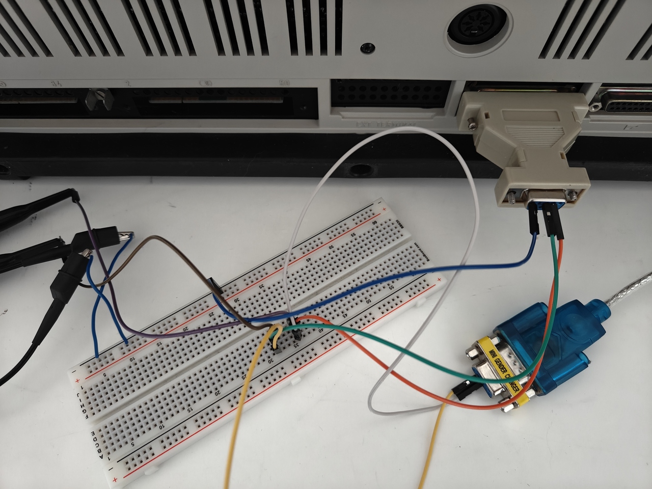
To read the raw signals, an oscilloscope is connected to the transmit, receive, and ground pins of the serial port. As shown below, I also use a DB25-to-DB9 adapter.
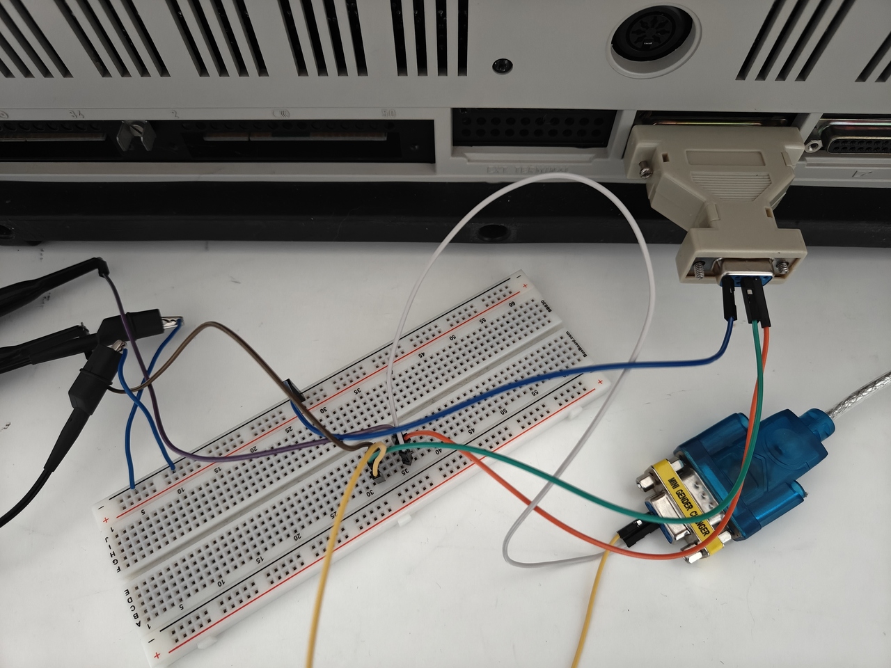
The female DB9 end of this adapter exposes the RxD (receive), TxD (transmit), and ground signals on pins 2, 3, and 5 respectively. Although the port exposes more signals, we can ignore them for this experiment. The RxD signal is wired to channel 1 and the TxD signal to channel 2 on the oscilloscope. In other words, the outgoing signal is monitored on the first channel and the incoming signal on the second.
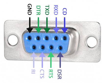
Via a breadboard, the RxD, TxD, and GND signals are also routed to a USB-to-serial cable so that the signals can be read on a modern computer. For this purpose, I use PuTTY, which is freely available.
Important
Connecting two serial ports requires using a so-called null-modem cable. Such a cable swaps the TxD and RxD lines between its two ends.
To mimic a null-modem cable, the RxD line (pin 2) on the P2000C side is connected to pin 3 on the USB-to-serial cable. Conversely, the TxD line (pin 3) is connected to pin 2. In other words, the TxD and RxD signals are swapped via the breadboard, corresponding to a null-modem configuration. Finally, all ground signals are connected, including the oscilloscope ground, to ensure a common reference.
Interrupt routines
According to the 8088 CoPower board manual (page 502), serial communication is performed through interrupt 0x14. Interrupt 14,0 sets the communication parameters, while interrupt 14,1 sends a single byte. Although the manual does not state the defaults explicitly, they appear to correspond to a baud rate of 1200, one stop bit, a byte size of 8, and no parity checking.
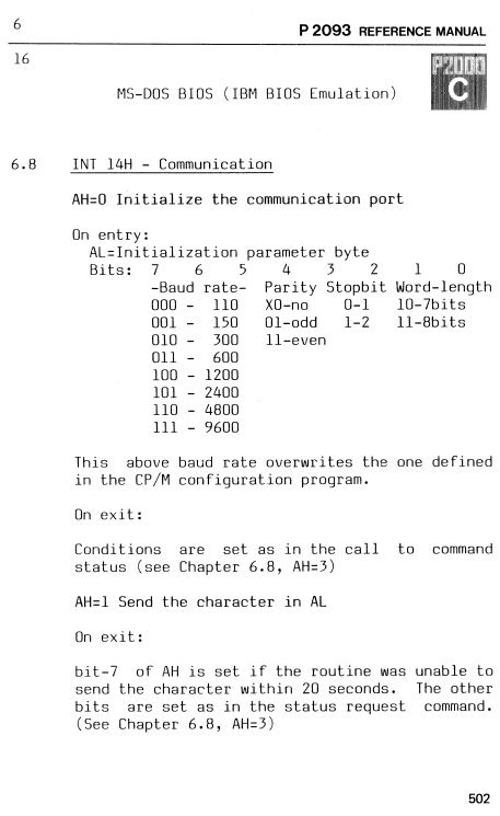
As shown in the previous post, we can use the MS-DOS debug program to write small snippets of assembly code. The following snippet sends 0x55 and 0xAA over the serial port.
mov ah,1
mov al,55
int 14
mov ah,1
mov al,aa
int 14
int 20
Important
According to the RS-232 standard, a logic 1 gives a low signal and a logic 0 gives a high signal. Furthermore, bytes are sent with their least-significant-bit (LSB) first. Every byte is preceded by a start bit (high signal) and ends with a stop bit (low signal).
On the oscilloscope, we see the result as shown in the image below upon running the program. First, a high start bit is seen. Next, the bits corresponding to 0x55 are received LSB-first and in inverted fashion. That means, a low signal corresponds to a binary 1 and a high signal corresponds to a binary 0. Since 0x55 corresponds to 0b01010101, the signals after the start bit correspond to low-high-low-high-low-high-low-high. Finally, a stop bit (low) is received.
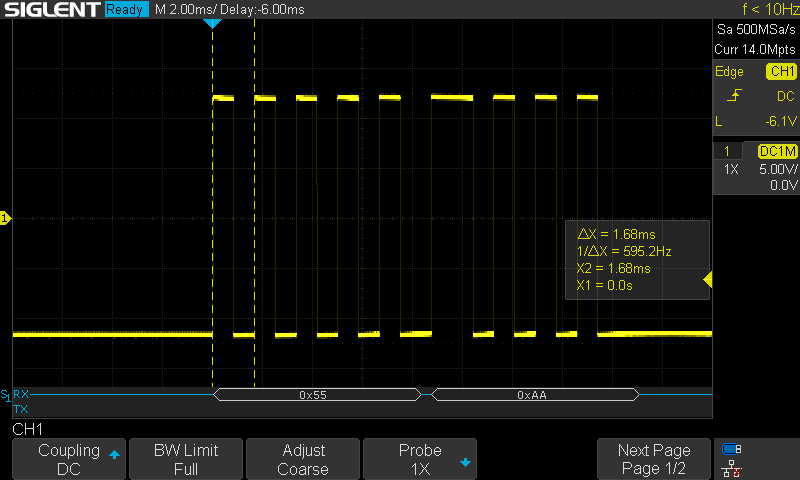
The next byte, 0xAA, shows a very similar pattern: a single high start bit, the byte encoded as high-low-high-low-high-low-high-low, and finally a low stop bit. The figure also shows two dashed lines marking the time interval of two consecutive pulses, one high and one low. Based on this interval, we can determine that 1200 bits per second are being sent, corresponding to the default baud rate.
Saying hello to the world
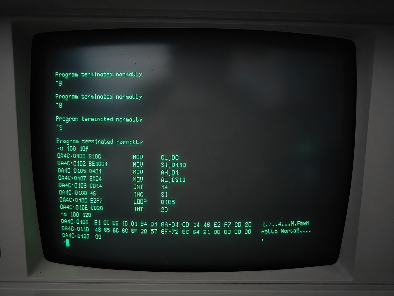
Let us try something a bit more interesting and send a sentence. The assembly snippet shown below loops 12 times over the characters in a string stored at location 0x110. Each character is sent to the serial port, after which the program terminates.
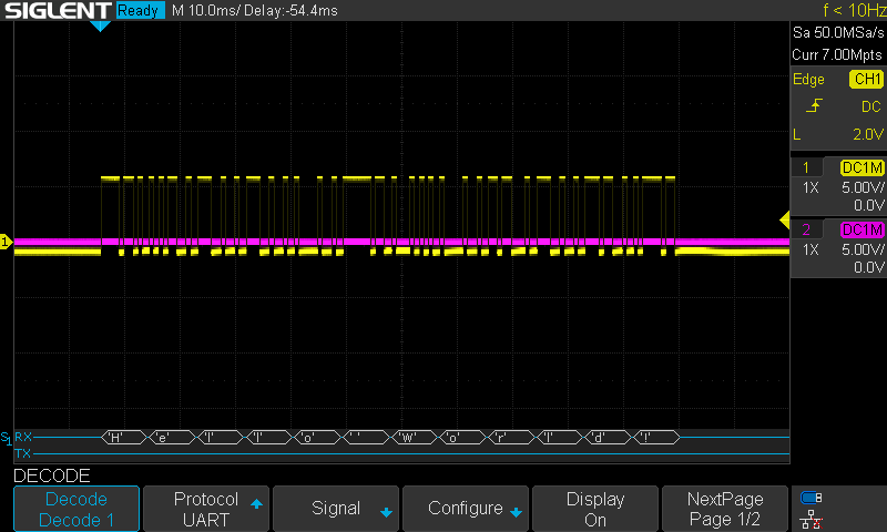
Upon executing this snippet, the oscilloscope confirms that we were able to send “Hello World!” over the serial port. Although not shown here, the laptop also receives the string “Hello World!”.
Changing the parameters
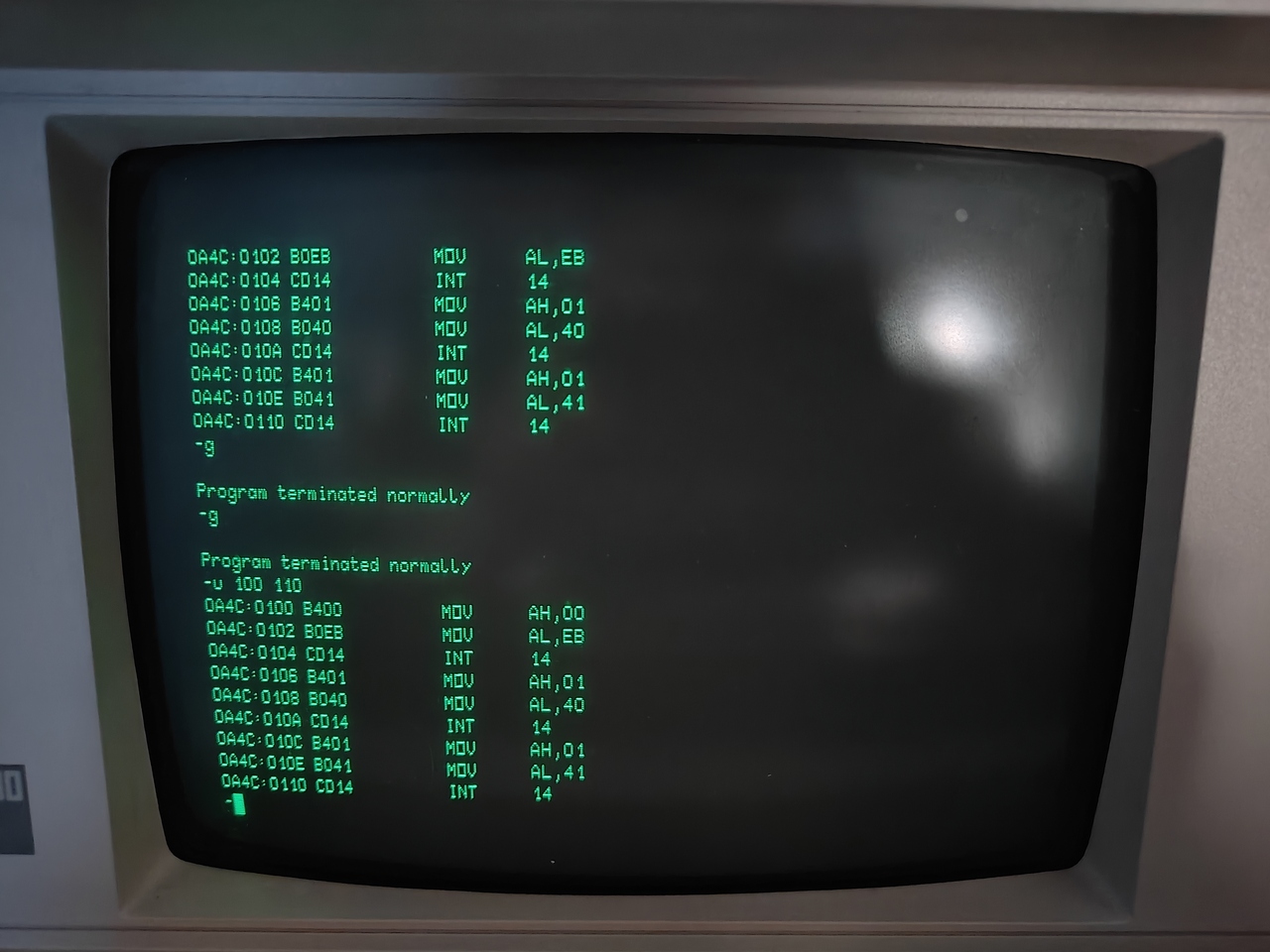
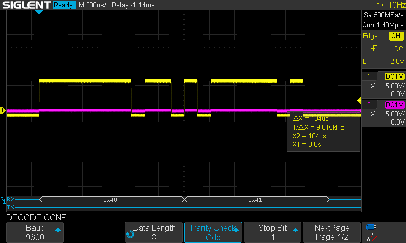
As mentioned earlier, we can also change the serial communication parameters via interrupt 14,0. Instead of the default baud rate of 1200, we set it to 9600. We also enable parity checking by enforcing odd parity via the parity bit. From the manual, this corresponds to setting 0xEB. To see the effect of parity checking, we send the bytes 0x40 and 0x41, corresponding to the ASCII characters @ and A. The complete code snippet is shown below.
Upon executing the program, we see the result on the oscilloscope as shown below. The start bit is indicated by the dashed lines. From its timing, we can confirm that the protocol indeed operates at a baud rate of 9600. Following the start bit, we see six consecutive high signals, then a low signal, then two high signals, and finally a low signal, the latter corresponding to the stop bit. As 0x40 is encoded as 0b01000000 and transmitted LSB-first, we would indeed expect six consecutive high signals. A binary 1 corresponds to a low signal, and the final binary 0, the MSB, yields a high signal. In total, the value 0x40 contains a single binary one, so the number of binary ones is odd. The parity bit is set to preserve odd parity, which corresponds to sending another 0, or high signal.
The next byte is 0x41, encoded as 0b01000001. In contrast to 0x40, directly after the start bit we see a low signal, then five consecutive high signals, followed by another low and then another high signal. At this point, the parity bit must ensure odd parity. Since 0x41 contains two ones, the parity bit must also be set to 1 so that the total number of ones remains odd. Thus, a low signal is received, followed by another low signal for the stop bit.
Outlook: File transfer
Using the serial port, we can transmit data between the P2000C and a modern computer. That opens the door to file transfer. By writing a small assembly program on the P2000C side, we can read bytes from the serial port, store them in memory, and finally write them to a file on a floppy. Since the highest accepted baud rate is 9600, this places an upper limit on transfer speed. Assuming the received bytes can be stored in memory at maximum efficiency, 9600 baud corresponds to approximately 0.94 KiB/s, or 0.85 KiB/s with parity checking enabled. A full 720 KiB floppy disk would therefore take almost 13 minutes to transfer.